MARIBOR KORUZA TEST NETWORK

WHAT?

KORUZA test network is connecting several locations in the center of Maribor. Wireless optical units are deployed in wlan slovenija network to form an ultra-fast connection between nodes.

WHY?

Built for testing the performance and reliability of wireless optical system KORUZA in order to enable further improvements, as well as for providing ultra-fast connectivity for direct collaboration for all involved.

HOW?

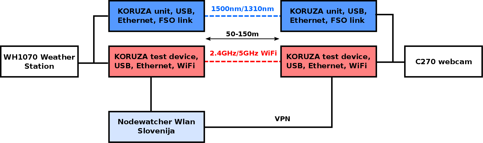
The network is deployed as a wireless mesh network with WiFi links serving as backup at approximately 20Mbps capacity and KORUZA links at 1 Gbps capacity, carrying the user data the majority of time, except when experimental alignment algorithms are tested.


KORUZA test network deployments:

Tkalka

Location: Tkalski prehod 4, 2000 Maribor, Slovenia

Units deployed on this location: irnas-3-2

More

Academia

Location: Glavni trg 17b, Maribor, Slovenia

Units deployed on this location:
irnas-2-1
irnas-3-1
irnas-4-1

More

GT22

Location: Tkalski prehod 4, 2000 Maribor, Slovenia

Units deployed on this location: irnas-4-2

More

Narodni dom

Location: Ulica Kneza Koclja 9, Maribor, Slovenia

Units deployed on this location: irnas-2-2

More

Interested in the real time performance of all deployed KORUZA links?

Go to Nodewatcher

WORLD WIDE KORUZA

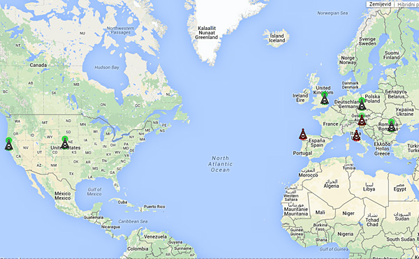
World Wide KORUZA experiment is the worlds first free-space optical coordinated experiment, deploying KORUZA at various locations around the globe for 6-12 months to evaluate the communication channel as well as the system performance, creating the first open data set on performance of a FSO system and the communication channel. We are inviting community networks and research institutions to participate in the experiment and sponsor deployments.

KORUZA AS A RESEARCH TESTBED

Experimental evaluation of FSO systems is traditionally associated with high costs and design complexity due to the high complexity of currently available systems and their significantly integrated nature. Often this prohibits researchers to modify systems and test their work, requiring them to construct their own systems. KORUZA as an open-source system mitigates these problems, the design transparency enables simple modification and adaptation for a range of purposes. A local performance baseline is created over the period of 6-12 months, enabling researchers to later modify the devices, improve them with their own transceivers, apply control and auto-tracking algorithms or modify otherwise and compare results to the baseline.

KORUZA FOR COMMUNITY NETWORKS

For community networks, KORUZA offers an alternative to often congested RF spectrum, ready to be tested. We are inviting networks to deploy the experimental links in their networks, pass real data through it however still keep the current RF links for the experimental duration as the fall-over option. The information gathered and findings from this experiment will feed back to the design and enable everyone to construct units on their own at a later time, deploying them in the network.

EXPERIMENT DESIGN

Leading motivation for launching the experiment is properly testing KORUZA system in real-world scenarios over a longer period of time, making it ready for an open-source release and creating an open data-set on FSO channel behaviour at a large number of locations. Additionally we want to establish a testbed and development basis for the FSO research.

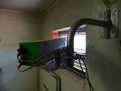
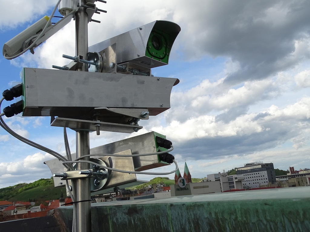
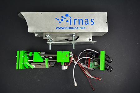
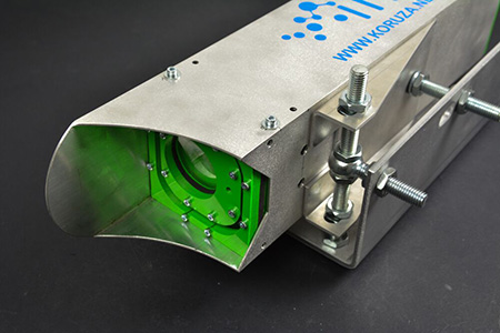
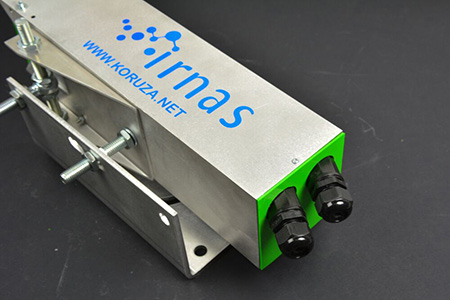
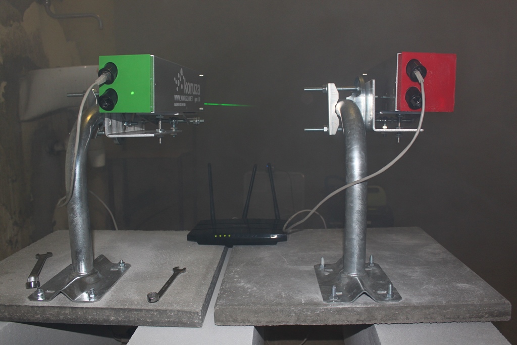
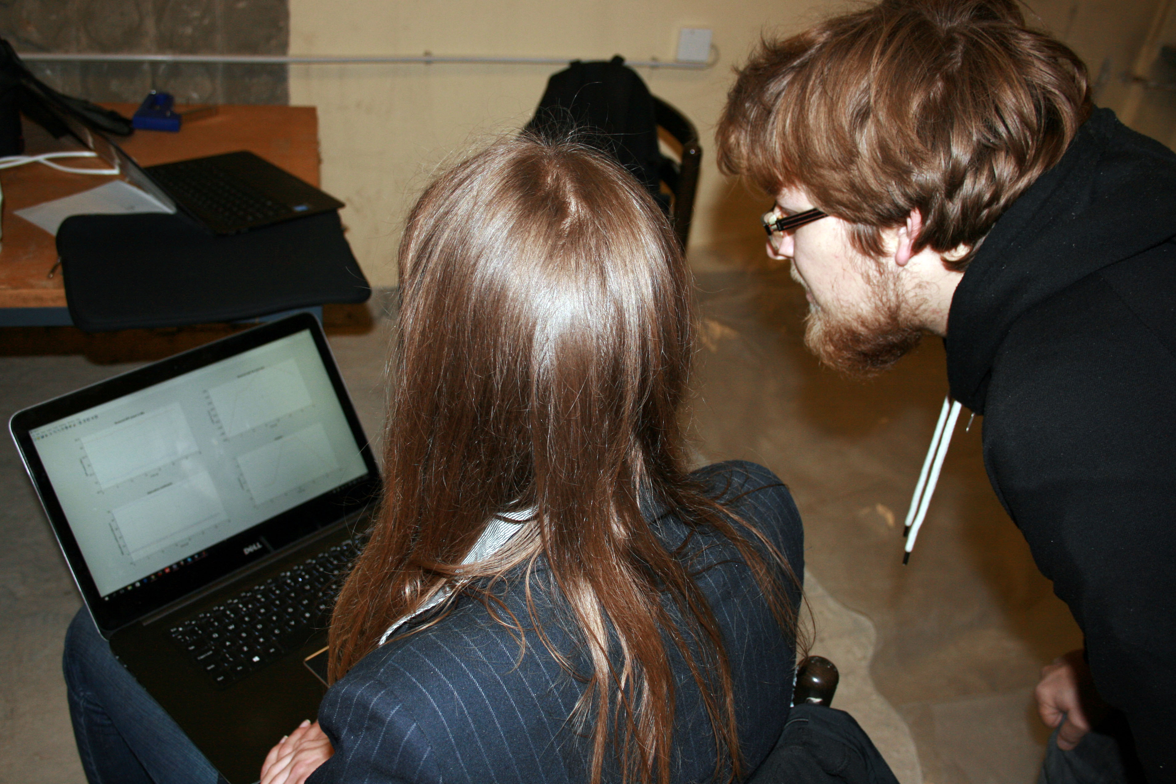
KORUZA experiment consists of two devices, one at either side of the link between buildings or structures 50-150m apart with a clear line of sight. Every device is extended with test equipment and sensors to evaluate the performance, link properties as well as observing environmental parameters. Measurements are collected at the rate of 1Hz, except the optical received power at the rate of 10Hz, made available in real time through nodewatcher platform. Test units are a part of the Wlan Slovenija community network, using the VPN service to connect to the server and establishing a data collection link.

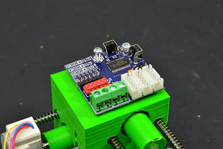
Every communication unit is equipped with the range of sensors to monitor the following parameters:

  • optical communication module (Temperature, Voltage, TX power, TX current, RX power, Link LOS state)
  • structure monitoring (Temperature 3D printed structure, Temperature enclosure, accelerometer)
  • control system and environment (Voltage, Ambient light, Temperature)

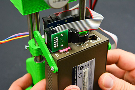
The test device is deployed next to ever unit to generate traffic and test for packet loss, aggregate all measurement and connect to the internet. It consists of:

  • openwrt capable 1Gbps router (WR1043 v2, WDR4300...)
  • USB webcam C270 (one side of the link)
  • USB link to KORUZA
  • USB weather station WH1080 (only on one side of the link, Temperature, Relative humidity, Rain, Wind speed and direction)

EXPERIMENTAL DEPLOYMENT SET

Participants in the experiment receive the assembled, calibrated and tested KORUZA devices ready to install, containing the following:

  • assembled, calibrated and tested KORUZA generation 1.0 pair
  • 2pcs KORUZA test devices
  • mounting kit for wall or railing
  • WH1080 weather station (sourced by the experimental partner)

Participants are required to:

  • make sure deployment locations have uninterrupted mains or 12V DC power supply and Ethernet internet uplink
  • ensure stable mounting (railings, wall, optionally free standing concrete blocks)
  • deploy and maintain the equipment for the duration of the experiment
  • keep devices unmodified unless otherwise instructed for the duration of the experiment
  • provide feedback

PARTICIPATION

The experiment is open for anyone to participate in, however we call for sponsorship and donations to be able to construct experimental devices and prepare them for deployment. Experimental equipment is provided by Institute IRNAS Rače and sponsored by partners, with the estimated equipment cost of approximately 1500EUR per setup. These funds go towards material end equipment costs (40%), development costs (~20%) and work costs (~40%).

To participate in the experiment please send us an email with organization details, proposed deployment location (GSP coordinates of link endpoint locations) and desired duration (6 or 12 months). Short description of currently running FSO experiment at location, if any, is welcomed as well.

First open-source testing facility

For conducting experimental work on free space optical (FSO) communication systems.
For testing and monitoring system performance exposed to variety of naturally occurring factors in the controlled environment.
For extensive analysis of any other free space system, utilising laser or other wireless, light.
To evaluate suitability and performance of prototypes, explore alternative construction solutions and advance the development process.

The main idea behind the development of such facility was lack of more widely available test equipment and appropriate space, where low cost FSO systems in development could be tested.

Following our open-source approach, experimental designs and detailed hardware and software documentation will be available for reproduction by other research groups and hackspaces.

Test Facility Specifications

test-facility-diagram
Length50 m
Width2 m
Hight1 m
VentilationFan with airfow rate 3000 m3/h, all air in the tunnel is changed in less than 2 min.
Measurement sensorReal-time monitoring of visibility, temperature, humidity and pressure on multiple points in the tunnel.
Data collectionWebsocket protocol, real time monitoring.

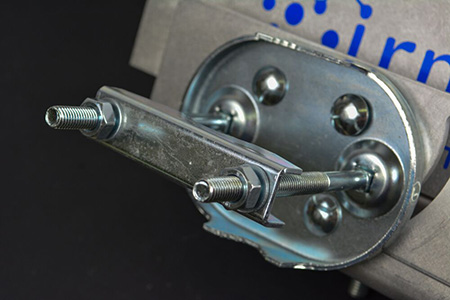
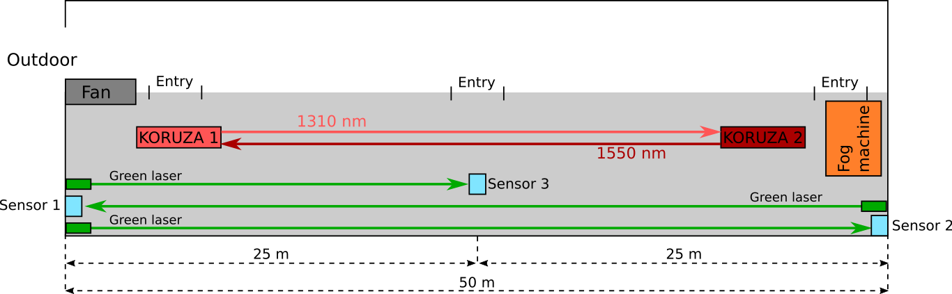
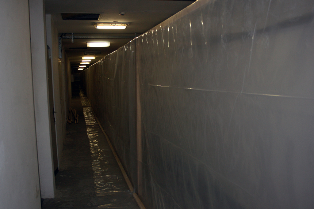
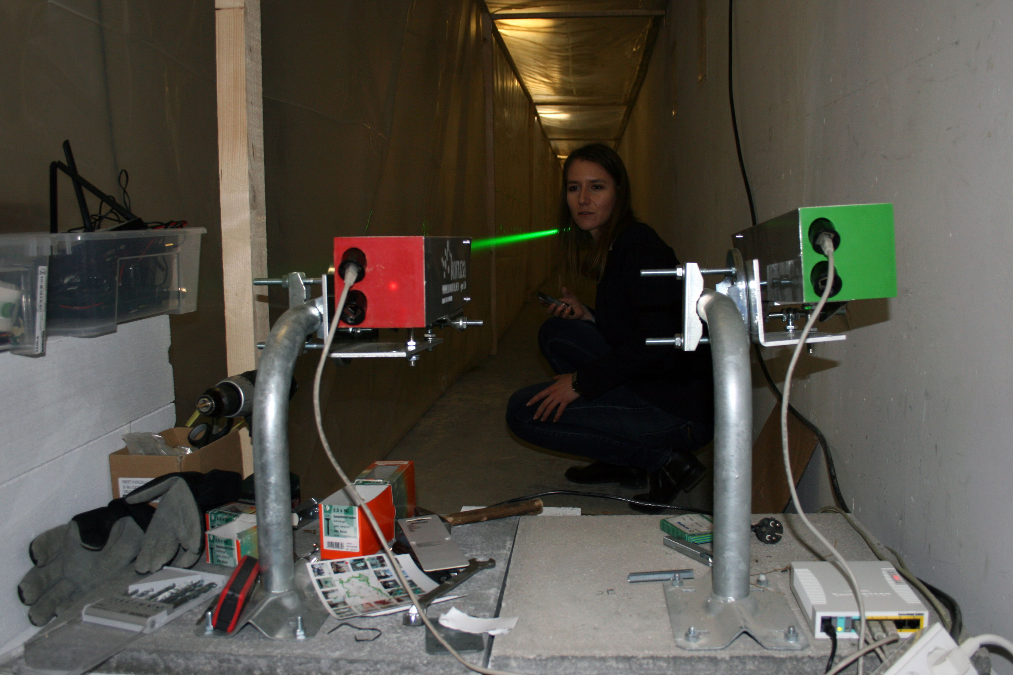
All the experiments are performed in a 50m corridor, 2m high and 1m wide, constructed using clear PVC foil draped over rigid, wooden frame inside a dark hall. Tunnel can be entered trough double opening in foil located on both sides and in the middle. Up to three FSO links can bi set up parallel along the tunnel, each of them mounted on a railing, fixed in the concrete block, eliminating misalignment due to unstable mounting.

To simulate fog conditions fog is produced using the fog machine and uniformly distributed down the corridor using adequate ventilation. So far experiments indicate that using the fog machine results in realistic fog conditions, however dry ice and a signal flares are planned for use in the near future as well. Further systems, such as heating chambers, vibration measuring system and scintillation simulation experiment are currently under the development and should be installed in the facility soon.

Experimental Overview

The leading objective of the project is to provide comprehensive, well rounded set of experiments and tests, suficient to assess the performance of the FSO system in various, naturally occurring conditions. We aim to introduce alternative test methods and procedures, providing good-enough results for development purposes at afordable price and made them freely available to the research community.

Experiments focus on two aspects: assessment and analysis of the system and its components as such and performance evaluation under exposure to various stress factors.

Main areas of interests and corresponding experiments:

Knowing characteristics of a laser beam, i.e. its spatial energy distribution, is essential for most wireless optical applications. The beam profile is used to characterize the quality of optical sources, observe effects introduced by lenses and other optical components. Utilising NIR pixel sensor unit coupled to a low-cost and open-source CNC machine movement system, an alternative beam scanner system was designed, suitable for producing a 2D scan of emitted optical power at a fixed distance from the source. Multiple 2D scans, taken at varies distances from the optical source are used to create a volumetric model of power distribution of an optical beam.
Often,finding exact consequence of replacement or adjustment of various system components is challenging or even impossible task, due to constantly changing environmental and other external variables. In test facility external changes are minimised and closely monitored using build-in test units, collecting data at the rate of 10Hz, allowing isolation and objective assessment of a single variable.
For terrestrial FSO systems, primarily located in urban areas offering mid-range connections, the leading cause of attenuation is presence of aerosols such as fog, smoke or dust in the atmosphere, due to scattering and absorption of the optical beam. Fog is composed of dispersed water droplets, generally between 10-15 microns in diameter, which is close to the near IR spectrum, thus Mie scattering, which appears when particles present in the atmosphere and the wavelength are comparable in size is present. In an indoor experiment, closely mimicking ambient conditions in the case of fog, smoke or both, outdoor conditions are simulated in a controlled manner, using fog machine, dry ice and a signal are. Controlled conditions allow performance of reliable measurements, otherwise often not possible due to irregularity and inhomogeneous distribution of the natural fog.
Uneven exposure to the Sun and sudden or gradual variation of the temperature of either surrounding atmosphere, mount or enclosure can lead to gradual degradation of the link or even complete loss due to physical deformation of components and consequential misalignment. Depending on the material used, daily and seasonal temperature variations can result in thermal expansion which causes periodical misalignment of the link. Data analysis of current link deployments suggest strong correlation between day-to-night temperature variation and link availability, however exact cause of link degradation remains unknown. Artifcial variation of the temperature of the unit itself or just the surrounding air can help to determine the extent to which the link is affected and find potential cause of impairment.
Another phenomenon potentially contributing to link loss is scintillation - optical turbulence resulting from small temperature variations along the link path. Inhomogeneous temperature distribution of the atmosphere causes varying refractive index along the link and thus scattering of the beam at different angles. Consequentially fluctuations in received power due to redistribution of intensity within the beam may appear. Although the research indicates scintillation is not a mayor concern for optical links shorter than 500m, variance of the optical power can be compared for the monitored link inside test facility and outside link of same length, as the scintillation in closed dark space should be minimal.
High level of background light, such as on a very sunny day or at the direct exposure of the receiver to the sunlight at sunrise and sunset, can alter the reliability of receiver readings due to high noise levels. Effect is hard to detect and often attributed to other factors, as it usually coincide with the temperature variation. Similar situation can be replicated by pointing strong white light source into the other unit at different angles while closely monitoring sensor readings.
Besides unavoidable severe weather conditions and physical obstacles on the link, the mounting environment is one of the leading factors contributing to misalignment and potential degradation of the signal. In contrast to changes in the atmosphere, loss is contributed to the temporal or prolonged misalignment of two units and not scattering of the beam. As units are usually mounted on a building, either rooftop or wall, building vibrations can have significant impact on the link performance, specially in urban environment due to motorways, public transport such as under and overground railways, construction work and also mechanical equipment present in the building itself. Another problem may arise due to wind induced movement of buildings, railings and unit itself, potentially problematic in mounting on tall structures.

Questions?

Do you have more question or you would like more info? No problem, just contact us.